
Retrieve The TACH Signal
- Gas Engines
- Diagnostic Port
- Find the TACH signal from the ECU
- IGN signal from diagnostic conenctor in engine bay
- Negative connection on distributor (if applicable)
- Wrap wire around a spark plug.
- Diesel Engines
- Diagnostic Port
- TACH signal from ECU
- Sensor on Alternator output (before the rectifier diodes)
- Hall effect or IR sensor mounted behind a pulley. should be able to count how fast the holes in the pulley go by. (Technically this would work on a gas engine too)
What You'll Need

- Arduino (or any other micro, i guess)
- I used an Arduino Leonardo and later a atmega 328p with uno bootloader to make it fit better in the car.
- A method to get the tach signal as seen in the beginning of the post
- I spliced the tach wire from the ECU
- Assortment of small / pasive components
- 7 150 ohm resistors
- 4 1 kohm resistors
- 4 2N3409 NPNs rated 140ma or more.
- Wire
- Used some ribbon cable for the tach signal
- Heavier stuff for gnd and power
- PCB
- Possibly used for final 328p build
- Tools
- Soldering iron
- Multimeter
- Wire stripper
- Knife
- Markers
- screw drivers etc
- Interface to show RPMs
- LEDs (1 per 1000 rpm?)
- Segment display
- I used two 2 digit 7 segment displays for 4 digits total.
- Serial character LCD
- Some sort of DIY tach dial
- Etc
Some Theory Crap
The Segment Display

Segment displays always have a shape of a number 8 while un-powered, but when of these segments are lit by a LED (that lights only that section) it can create any digit between 0 and 9. The color of the digit and the color of the LED changed the final illuminated color. They also generally have a common cathode (ground) or anode (positive). That means if it was common cathode, all the ground ends of the segment LEDs would be connected and would go to ground. To turn on a segment, you simply connect one anode of a segment LED to positive voltage and it will flow through to ground via the common cathode (but not any other segment). I must also note that most segment displays don't have resistors included, so you must have your own externally just like a regular 5mm LED.

Here is an example internal scheme of a common anode segment display. Positive voltage will always be applied to the anode point, but nothing will light until a ground is connected to one of the letter points.

In this image you can see how the segments are labeled. This is very important when it comes to programming.

This image helped figure out how to wire the segments and the correct orientation of the display. The left image is a top vied of the display. In all theses images of the display in this post you can see the DP or points and they are how i knew the orientation of the pins. It's kinda hard to explain but the bottom of the display has the points, of course, and we see that the scheme has 1 starting on the bottom left with the points on the bottom.
Multiplexing The Display
Ok, lets get to the MP (multiplex) explanation. MP works because of POV or persistence of vision. A good example of POV is a LED that is changing in brightness. By switching the LED on and off really fast it looks like the LED is changing in brightness. When its dimming the LED is blinking off more than it is blinking ON. So: full brightness = on all the time, off none of the time. half brightness = on half the time, off the other half. These "halves" are just fractions of seconds. The human eye cant see it blinking because its doing it so fast.
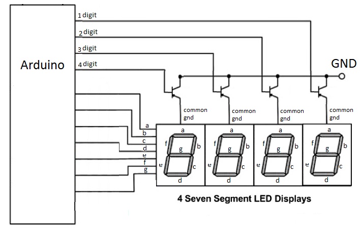
Lets say you have a scheme like above. All the "a" segments are connected and go to pin "a" on the Arduino and so on and so forth for b to g. All of the pins are currently "LOW". Then you turn "a" HIGH, but nothing happens. Then "digit 1" is HIGH and segment "a" of digit 1 lights up. Then digits 2, 3, and 4 are HIGH and now all the "a" segments are on. Lets say you wanted a 9 on digit 1 so "a", "f", "g", "b", and "c" are high, but now all the digits have a 9 so digits 2, 3, and 4 are LOW to make just digit 1 have a 9. but what if you want to have digit 2 have an 8 too. making all the segments and digit 2 HIGH would cause digit 1 to have a 8 too.
This is how you'd have a 9 on digit 1 and a 8 on digit 2: "a", "f", "g", "b", and "c" are HIGH and then digit 1 is high. Then digit 1 is LOW. "e" and "d" are HIGH. Then digit 2 is HIGH. Then digit 2 is LOW. "e" and "d"are LOW. REPEAT. That whole digit 1 off then digit 2 on thing is happening so fast it looks like digit 1 never turned off and digit 2 is being controlled separately.
In coding reality this is done much faster than on / off. The theory is the same for doing 4 digits. If enough digits are added either the Arduino (this first) or the electronics wouldn't be fast enough and it would look like some are off or dimming.
Using the TACH Signal
This greatly depends on what signal you use. If you're grabbing the signal from the ECU it will probably be a 12v square wave. The way i figured it out was partly do to forums and just simple logic of what the multimeter is reading. I put one lead to GND and the other to the TACH wire and then flipped through the multimeter settings. DC gave nothing (so not PWM), AC gave nothing (would be strange anyways), but Hz did read something. It idled at about 150Hz and the Hz went up as i revved the engine, so from that I figured it out without a oscilloscope. This, this, or this would've been nice though.

The Build
Segment Display

If the heading wasn't obvious enough, the first thing I did was to make the segment display module. Since I was doing this with only parts I had on hand and a segment display was one of the easier things to make (second to the LEDs, but that doesn't provide enough feedback). I was thinking of what my display should be and I remembered the segment displays I got from somewhere (no idea hah) and thought they'd do the job just fine. Then the debate was how many digits would I use? One and just do it per 1000 RPM? nah lame. I decided to go with the full number for ex: 4211 RPM. I cleaned off the solder blobs (I had previously used these) and glued the two displays together for the four in the picture. I also put a simple PCB underneath it to make it more stable and soldering easier. I also "sharpied" the white / red case to make it look better.
 Here's a good ol' classic lesson for all of us (again). Test the parts before you put them together; apparently one of the LEDs went out on the display, so the project stopped for a bit. I ordered a combined 4 digit 7 segment display for about two dollars (connecting the two segments was a pain anyways). This one is a Common Cathode design so I used a ULN2003 instead of the annoying individual PNP transistors from the Common Anode display. Instead of going full speed ahead, this time I built just the segment display on a bread board with an arduino and the ULN2003.
Then I got some code working (see below) that picks a random number and displays it on the segments. Now i just have to get the motivation to go out in the cold and get the arduino reading the tach signal. I did go with the ECU method, so its just 12v, GND, and the tach signal wires hanging out of my dash.
#define digit1Pin 3
#define digit2Pin 5
#define digit3Pin 6
#define digit4Pin 9
#define segAPin 2
#define segBPin 4
#define segCPin 7
#define segDPin 8
#define segEPin 10
#define segFPin 11
#define segGPin 12
// variable for storing separate
// digits
int oneDigit = 0; // ones
int tenDigit = 0; // tenths
int hunDigit = 0; // hundreds
int thoDigit = 0; // thousands
long previousMillis = 0; // will store last time random number was changed
long interval = 750; // interval
byte currentDigit = 0;
void setup() {
//Serial.begin(9600);
for(int x=2; x<13; x++)
{
pinMode(x,OUTPUT);
digitalWrite(x, LOW);
}
FullDigitFlash(100,3); //time in miliseconds, repeat flash x times
}
void loop() {
//this needs to be on a seperate loop so the multiplexing can work
unsigned long currentMillis = millis(); // log where we are in terms of the next number
if(currentMillis - previousMillis > interval) //check if we want to get a new number
{
// save the last time you blinked the LED
previousMillis = currentMillis;
CalculateDisplayNumber(random(0,10000)); //I can put in any number i want here
}
DigitUpdate();
delayMicroseconds(100); //make digits show proper brigtness. with out this the lighting looked uneven
}
void CalculateDisplayNumber(int numberToDisplay)
{
// extra variable for storing
// other mathematical operations
int hundreds = 0;
int tenths = 0;
// two prelimenary operations
hundreds = numberToDisplay % 1000;
tenths = hundreds % 100;
// separating the ones digit
oneDigit = tenths % 10;
// separating the tenths digit
tenDigit = (tenths - oneDigit)/10;
// separating the hundreds digit
hunDigit = (hundreds - tenths)/100;
// separating the thousands digit
thoDigit = (numberToDisplay - hundreds)/1000;
}
void DisplayANumber(byte digitToDisplay, byte numberToDisplay)
{
if(numberToDisplay == 0)
{
digitalWrite(segAPin,HIGH);
digitalWrite(segBPin,HIGH);
digitalWrite(segCPin,HIGH);
digitalWrite(segDPin,HIGH);
digitalWrite(segEPin,HIGH);
digitalWrite(segFPin,HIGH);
digitalWrite(segGPin,LOW);
}
else if(numberToDisplay == 1)
{
digitalWrite(segAPin,LOW);
digitalWrite(segBPin,HIGH);
digitalWrite(segCPin,HIGH);
digitalWrite(segDPin,LOW);
digitalWrite(segEPin,LOW);
digitalWrite(segFPin,LOW);
digitalWrite(segGPin,LOW);
}
else if(numberToDisplay == 2)
{
digitalWrite(segAPin,HIGH);
digitalWrite(segBPin,HIGH);
digitalWrite(segCPin,LOW);
digitalWrite(segDPin,HIGH);
digitalWrite(segEPin,HIGH);
digitalWrite(segFPin,LOW);
digitalWrite(segGPin,HIGH);
}
else if(numberToDisplay == 3)
{
digitalWrite(segAPin,HIGH);
digitalWrite(segBPin,HIGH);
digitalWrite(segCPin,HIGH);
digitalWrite(segDPin,HIGH);
digitalWrite(segEPin,LOW);
digitalWrite(segFPin,LOW);
digitalWrite(segGPin,HIGH);
}
else if(numberToDisplay == 4)
{
digitalWrite(segAPin,LOW);
digitalWrite(segBPin,HIGH);
digitalWrite(segCPin,HIGH);
digitalWrite(segDPin,LOW);
digitalWrite(segEPin,LOW);
digitalWrite(segFPin,HIGH);
digitalWrite(segGPin,HIGH);
}
else if(numberToDisplay == 5)
{
digitalWrite(segAPin,HIGH);
digitalWrite(segBPin,LOW);
digitalWrite(segCPin,HIGH);
digitalWrite(segDPin,HIGH);
digitalWrite(segEPin,LOW);
digitalWrite(segFPin,HIGH);
digitalWrite(segGPin,HIGH);
}
else if(numberToDisplay == 6)
{
digitalWrite(segAPin,HIGH);
digitalWrite(segBPin,LOW);
digitalWrite(segCPin,HIGH);
digitalWrite(segDPin,HIGH);
digitalWrite(segEPin,HIGH);
digitalWrite(segFPin,HIGH);
digitalWrite(segGPin,HIGH);
}
else if(numberToDisplay == 7)
{
digitalWrite(segAPin,HIGH);
digitalWrite(segBPin,HIGH);
digitalWrite(segCPin,HIGH);
digitalWrite(segDPin,LOW);
digitalWrite(segEPin,LOW);
digitalWrite(segFPin,LOW);
digitalWrite(segGPin,LOW);
}
else if(numberToDisplay == 8)
{
digitalWrite(segAPin,HIGH);
digitalWrite(segBPin,HIGH);
digitalWrite(segCPin,HIGH);
digitalWrite(segDPin,HIGH);
digitalWrite(segEPin,HIGH);
digitalWrite(segFPin,HIGH);
digitalWrite(segGPin,HIGH);
}
else if(numberToDisplay == 9)
{
digitalWrite(segAPin,HIGH);
digitalWrite(segBPin,HIGH);
digitalWrite(segCPin,HIGH);
digitalWrite(segDPin,LOW);
digitalWrite(segEPin,LOW);
digitalWrite(segFPin,HIGH);
digitalWrite(segGPin,HIGH);
}
if(digitToDisplay == 1)
{
digitalWrite(digit1Pin, HIGH);
}
else if (digitToDisplay == 2)
{
digitalWrite(digit2Pin, HIGH);
}
else if (digitToDisplay == 3)
{
digitalWrite(digit3Pin, HIGH);
}
else if (digitToDisplay == 4)
{
digitalWrite(digit4Pin, HIGH);
}
}
void DigitUpdate()
{
if(currentDigit==0)
{
digitalWrite(digit1Pin, LOW);
digitalWrite(digit2Pin, LOW);
digitalWrite(digit3Pin, LOW);
digitalWrite(digit4Pin, LOW);
DisplayANumber(1,thoDigit);
currentDigit++;
}
else if(currentDigit==1)
{
digitalWrite(digit1Pin, LOW);
digitalWrite(digit2Pin, LOW);
digitalWrite(digit3Pin, LOW);
digitalWrite(digit4Pin, LOW);
DisplayANumber(2,hunDigit);
currentDigit++;
}
else if(currentDigit==2)
{
digitalWrite(digit1Pin, LOW);
digitalWrite(digit2Pin, LOW);
digitalWrite(digit3Pin, LOW);
digitalWrite(digit4Pin, LOW);
DisplayANumber(3,tenDigit);
currentDigit++;
}
else if(currentDigit==3)
{
digitalWrite(digit1Pin, LOW);
digitalWrite(digit2Pin, LOW);
digitalWrite(digit3Pin, LOW);
digitalWrite(digit4Pin, LOW);
DisplayANumber(4,oneDigit);
currentDigit=0;
}
}
void FullDigitFlash(int time, byte repeatTimes)
{
for(int y = 0; y<repeatTimes; y++)
{
for(int x=2; x<13; x++)
{
digitalWrite(x,HIGH);
}
delay(time);
for(int x=2; x<13; x++)
{
digitalWrite(x,LOW);
}
delay(time);
}
}
Then I got some code working (see below) that picks a random number and displays it on the segments. Now i just have to get the motivation to go out in the cold and get the arduino reading the tach signal. I did go with the ECU method, so its just 12v, GND, and the tach signal wires hanging out of my dash.
Did you ever finish this? I'm actually doing the same thing, only I'm making a shift indicator instead of a tachometer and all I need to do is figure out the tach input and associated code.
ReplyDeletewell its pretty much 90% done. its cold outside and im too lazy to carry all my electronic shit cross campus (im in college) to do the final "fitting" (5v for the arduino from the car, and the level shifting 12v signal to a 5v arduino compatible one).
Deleteso do you have your tach signal sorted out on the car ? do you know where it is or what type of signal it is?
Tachometers are great devices to work with. You can have detailed information about the Tachometer
ReplyDeleteCan you detail what you did to make the Arduino read the tach signal and output the rpm?
ReplyDeleteI am just wondering if you ever got this working? I want to simply read the RPMs I do not even care to display them I just want to read them from serial connection from the ECU.
ReplyDeleteIt was a 12v signal coming out of the ECU so if you step it down to into the 5v range, the arduino analog pin should be able to read it. Itd be handy to have an oscilloscope to see what kinda signal it is for sure.
DeleteThere is SHOCKING news in the sports betting world.
ReplyDeleteIt's been said that every bettor needs to see this,
Watch this or quit placing bets on sports...
Sports Cash System - Advanced Sports Betting Software