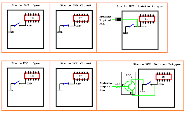
Button pulled down to GND
This method is much easier to toggle and is what my RC remote has. One side of the so called "button" is connected to GND, the other is connected to the IC of the TX. The pin of RC transmitter IC that the button is connected to is: +3v when the button is open and 0v when closed. so that means the button is "pulled" down to ground when closed. To trigger this button with a Arduino, it is quite easy; all that is needed for this type of switch is a diode from the RC transmitter IC pin to a Arduino digital pin. Then the following code. I believe the pin only needs to be set LOW once (the first line of code) but im not sure.
digitalWrite(RCtxBtn, LOW); // RCtxBtn is the number of the digital pin
pinMode(RCtxBtn, OUTPUT); // Pull the signal low to activate button
delay(500); // Wait half a second
pinMode(RCtxBtn, INPUT); // Release the button.
delay(500); // Wait half a second
Button pulled up to +3v
This method, on the other hand, is a little harder to implement, but still easily done. This method is used when the IC side of the switch when open is GND and the other side is +3v. Then when the button is pressed, both sides become +3v So that means the button is "pulled" up to +3v when closed. to trigger a button like this with a Arduino, a resistor and PNP transistor are needed. the PNP has thee pins; Emitter, Base, and Collector. Emitter is the "input", Collector is the "output", and the Base triggers the flow of current from the Emitter to the Collector. Emitter is connected to +3v , Collector to the IC side of the switch, and Base is connected to a 10k resistor and then Arduino Digital pin.
pinMode(RCtxBtn, OUTPUT);
digitalWrite(RCtxBtn, LOW); //trigger the button, yes LOW is "on"
delay(5000); //on for 5 sec
digitalWrite(RCtxBtn, HIGH); //release button
delay(5000); //off for 5 sec
Visual Explanation:

Dear Jordan!
ReplyDeleteAs I understood, the way you simulate the feature of a real buttonswitch, is that you use a diode to connect the digital pin of the Arduino with the high level pin of the transmitter IC. Then you pull the digital pin low. (The diode is missing in the attached picture however).
I try Ur solution.
Thank You for your rapid answer btw! ;)
Yours
Gergo
what attached picture?
DeleteThis comment has been removed by the author.
Deleteno, the diode is there, its black with the grey strip (showing direction of flow) right outside the black box.
DeleteDear Jordan,
ReplyDeletecompliments for your blog, it is very interesting! I read your post about the remote controller but I am getting crazy with my alarm remote controller. It has 2 pushbuttons, one to activate the alarm and one to deactivate it. The remote controller works with a 12 V battery.I would like to short-circuit the buttons using a transistor npn 2n2222a to control them with my raspberry pi. I connected one pin of the pushbutton (the one with positive voltage) to the collector and the other pin (the one with 0 voltage) to the emitter and the raspberry ground PIN. The base is connected to a digital PIN of the raspberry. When The digital PIN is high, 3.3 V, the push-button is short-circuited and the alarm is inserted.
The problem comes up when I connect, in the same, way the other push-button. In this case, both push-buttons seems short-circuited at the same time and the remote controller doesn't work.
Could you help me to understand what is wrong? I am a newbie and I don't know very well electronics. Thank you in advance for your help.
Lorenzo
Perhaps the board has some sort of multiplexing? That wouldn't be surprising on a remote with lots of buttons
DeleteIt could be... I don't know actually. Anyway, I finally solved the problem using 2 optocouplers LTV4N35 connecting its collector and emitter to the two wires of each button.
DeleteThe digital pin of my raspberry activates or deactivates the optocoupler. This system is simply and effective :-)