Friday, May 3, 2013

RC Power Wheels Jeep

This post is about the Power Wheels Jeep I found in my neighbors trash while working on the Racing Wheel project. I plan on slimming it down, PAINTING IT, and turning it into a RC Power Wheels (on a low budget).

When I saw it, I was thinking it would be very unlikely any thing was severely wrong with it. 

Sunday, April 28, 2013

DIY Computer Racing Wheel Setup

The main goal is to build a Racing Wheel for a computer out of a soon-to-be-scrapped 92 Ford Taurus. Since it's going to the scrap, it doesnt really matter what happens to it. Hehe. So, I've been taking apart random parts to learn about them. :) The  photos area bit lacking but should get the point across.

There she is :D

OBDuino Project

The goal of this project is to interface an Arduino with car OBDII diagnostics to display telemetry for the driver. This project first started because I wanted a tachometer in my automatic 2002 Prizm. I found one of those super cheap tachs on ebay, but hey, whats the fun in that? Here is a toyotanation (forum) post on that tach and install for most ~2000 Toyota Corollas. This tach works by reading the IGN or ignition pulse from the diagnostic port.

Wednesday, March 6, 2013

Disassembeling a LiPo

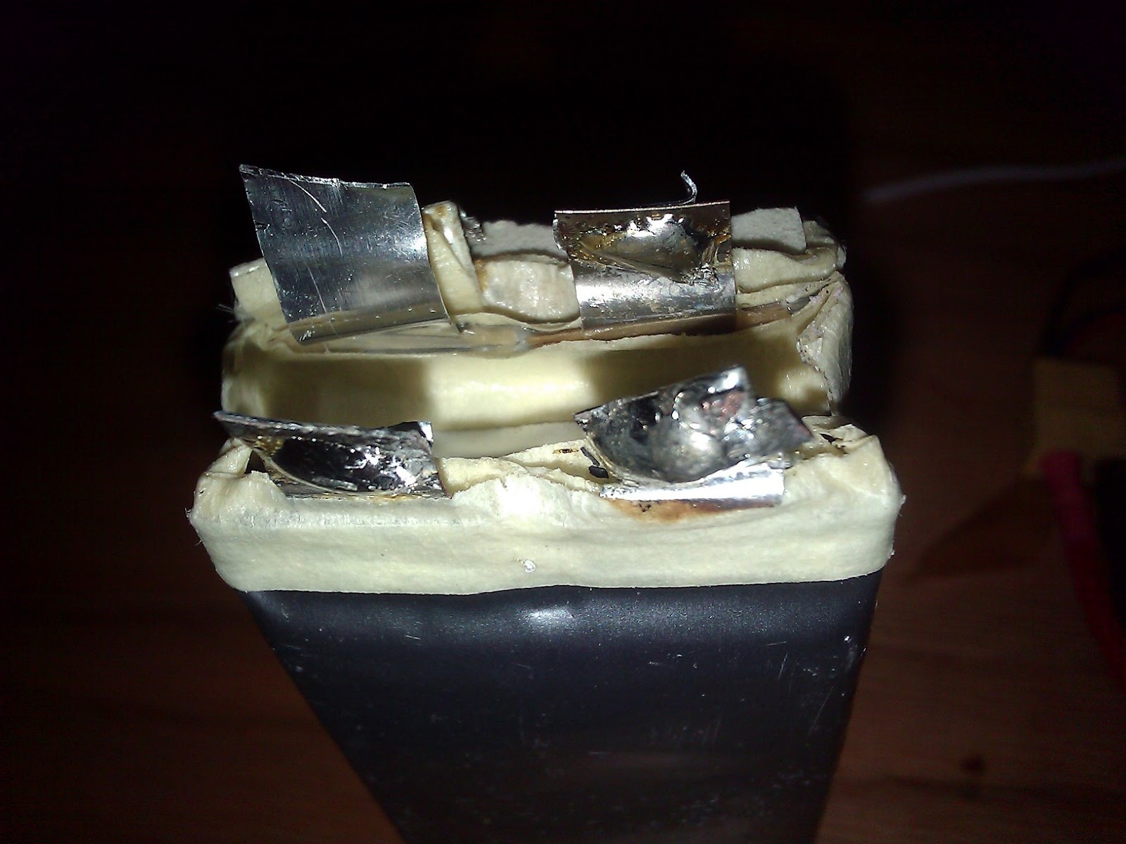
This is one of my first 3s LiPos that is pretty much useless now (wasn't damaged), so i decided to disassemble it.
Cut off the blue casing by taking an exacto knife. I cut a little notch and then it simply ripped down the case.

The balance connector and main terminal connectors

I didn't want to risk un-soldering, so, i carefully trimmed off the balance wires, then the main leads.  

To separate the cells, i used a plastic table knife and gently sawed them apart. The adhesive smelled really bad, but it at least it wasn't sweet ( a sweetish smell from a LiPo = fire).

As seen in the pictures, this 3S LiPo has three cells each with a nominal voltage of 3.7V and a capacity of 2200mah. Put three of these in series and you have 11.1V, the nominal voltage of a 3S LiPo battery. If the batteries is in series, the voltage increases, but the capacity is the same as the individual cells. In parallel the battery would have the same voltage as the individual cells, but the capacity of each cell is essentially "added". So, if these were wired in parallel, it would've been a 1S (3.7V) 6600mah LiPo battery.

And as the Mythbusters have said:
(All rights given to uploader and original content provider. I don't own this or the content.)

Yet Another Original Car Radio Aux Input Mod

Yeah, bad title, get over it.

Background

I got a new car because my 92' Taurus's ECM (the brain) decided to crap out. We decided it would be better to just get a new car. Oh, and this was in the middle of the interstate :D. Which meant that the motor suddenly stopped since nothing was controlling the motor electronics. Since i was going 70mph, it was quite easy to pull of to the side and think "what the hell" ?!?!?

I poked around craigslist and found one of the cars I've always wanted: a 1999 Mitsubishi Eclipse. This didn't work out because i'd know they were all owned by younger people and therefor shitily driven. Still wanting a Mitsubishi, i found a Lancer, but the same story. I settled on a 2002 Chevy Prizm for a good price. it doesn't have many features, but it gets 37 MPG. meh, it gets good mpg, "screw looks" i basically said. It actually had a CD player, so i didnt really mind no aux-in port. this soon changed.

While using it, i noticed the buttons were all extremely hard to push. Meh, whatever, i only need the main volume/power encoder, so i didn't really care. And then CDs stopped working. I'm screwed. I never listen to FM because i have no local Techno etc stations. i have ascended to the best music. So i took this radio apart, and surprise, surprise: pop all over the inside. It seem the previous owners spilled a bit. I started cleaning and soon realized that i couldn't do it by hand. So i walk over to the sink, fill it up with hot water and i wash my radio :D. FYI, it is the minerals in the water, not the H20 itself that fries electronics. Then i did a few rinse cycles in distilled water (pure H20), and dried it. The radio still works just as it did before the wash: no CD player.

Theory Stuff

I then began the same search as i did in my Taurus radio mod for the audio lines to the speaker amplifiers on the PCB and therefor bypassing the controls entirely and allowing a standard 3.5mm audio cable to be connected for aux-in. i was still unable to find the audio lines from the FM decoder to the mixer chip so i'm stuck without mixer controls on the radio (bass boost etc).

If your CD player still works and you just want aux out, then look at these sites: here and here. Note that the Prizm radio is essentially the same as the ones in those posts, so the mod works. i'd guess a lot of stock radios from the 2000's would have a similar layout and the mod would also work. This method allows you to still use the bass, treble and volume buttons etc on your radio with your aux device and the CD player still works when you take out the aux cable.

The Mod

Pull out the Radio

Use a screw driver to pry the black console frame off at the red line. Make sure you don't damage the dashboard foam/plastic stuff. Or you could some how pull out with some 90deg hook tool at the blue line. After you get a side loose, then just use your hands and follow the perimeter with your hands pulling out.

Pull the black casing off to the side to get the radio out. 

Take out the four yellow marked screws. Now, pull the radio out and up just over the shifter. Then, pull off the antenna connector and harness.  

Here's my radio before the mod.

Take off the mounting hardware and case

These plates are held on by a few small screws, and just pull off. Also, note that these are weird bolts, neither customary or metric sockets fit. I had to use a pliers.

These are the mounts for the radio to the car dash.One bracket per side. Three 8mm bolts each.

All the plates and brackets

Search for the magical mixer IC output lines

CD Player Mechanism below the top plate. 
This was simply puled out after the case screws were taken out.

The top PCB after taking out the CD player mechanism. Hot glued the cable to the PCB.

The bare PCB below bottom plate. Where ill find the input lines.

Labeled PCB

Mixer outputs to AMP.

Then i just soldered a 3.5mm audio cable to the pads, and soldered a ground.

Friday, February 1, 2013

FrSky Voltage Sensor

One of the reasons I choose to upgrade my Turnigy 9x to the FrSky system was the telemetry(2-way) mode. This gives me signal strength data and most of all, the RX has two analog ports. These two analog ports (3.3v!) can be used for anything with a range of analog values. For example, with a few resistors, i made a voltage divider so that the 12.6v of a lipo is scaled down to 3.3v where it is then sent to the 9x and read out as a battery voltage on the 9x lcd. no need for lipo alarms! I have the ER9x firmware which made the frsky mod possible. also required here.

RX Setup


Here is the schematic. The color dots are the resistor color codes. AIN is A1 or A2 on the RX. Only connect one +. so if you had a 3s batt, you would connect it 12v+ to the 3s resistor.

TX Setup

Hardware Setup

-Build the above circuit for the battery you are using
-Connect it to the battery and RX(dont mess up polarity!)
Turn on your TX
-Power the RX with a bec or something

Voltage Calibration 

model page 10/12 (Telemetry 1)
-A1 channel 11.1v 13.0 line is showing the voltage of the battery 11.1v is a calibration value, 13.0 in this example is the actual battery voltage it reads.
-To set this up, measure the voltage of your battery with a volt meter. 
-Now this voltage should be in this screen. adjust the 11.1v number until the 13.0 number is equal to the volt meter reading
-press exit when done. now you have "calibrated" A1. 
-also, the the "v" from 11.1v can be changed to A for ex to measure the amps the model is drawing (with that amp sensor of course).

Alarms

alrm --- < 0.0v
alrm  --- < 0.0v

These are alarms you can set so it will beep when it is below certain level. 
-Select the "---" and choose yellow, orange or red. these would be the level of the battery. 
-Now, you can change the sign (< or >)most people will use less than (<) then you could set the 0.0v parameter to the a voltage that is related to the yellow orange or red. FOR example

alrm Yel < 11.1v 
this means you would have a yellow alert when the battery on the model drops below 11.1v
alrm Red < 10.0v 
this means you would have a red alert when the battery on the model drops below 10.0v
alrm Yel > 11.1v
this means you would have a yellow alerrt while the battery on the model is above 11.1v
alrm Red > 10.0v
this means you would have a yellow alert when the battery on the model is above 10.0v

Same for if you had a battery on A2

Model page 11/12 (Telemetry 2)
-TxRSSIalarm is a value to set for when the TX signal is less that whatever value. lets you know when youre going out of range
-RxRSSIalarm is the same for telemetry signal from the rx
-mAhalarm is for alarming you when you have drawn x amount of amps from the battery
-ALTalarm is for if you have a baro sensor and it will alarm you if you have gone too high.
-gpsaltmain uses the gps as a baro instead of the separate baro

-Custom Menu this allows you to change what values show on your Telemetry screen while using the TX. i did A1 A2 RSSI and TSSI


will add more pics :)!!

Assemble a HK 2-axis FPV Mount

I bought this to fill up one of my HK orders. Here is how i put it together

The parts in the bag.

The linkage endings. Press the little metal balls into the plastic.

Put them on the shaft like so.

Grab two servo horns like so. 

See if the holes will fit the bottom piece like so. If so, then use screws to hold the horn on to the piece. If it doesn't fit, you will have to use hot glue to hold it in place.


Like so.

Testing with a servo. Make sure you center the servo somehow before screwing it on.

Put the bearings in to the arms. Everything is press fit. Now, insert the camera mount plate into the bearings.

Put the little bearing covers on.

Once you have that, carefully spread the arms so that the base plate fits in (see bottom).

Put the servo arm on with the servo centered like so.

Use the itsy bitsy screws from the pack to attach the linkage to the servo arm and the base arm. i used a spacer on the servo arm for better movement. To get the angles right, i held the servo to the camera plate with my hand, and then used the HK servo tester to see what range the servo moved the camera plate. Then i moved it a bit up or down and repeated until the camera plate moved in a range i wanted.