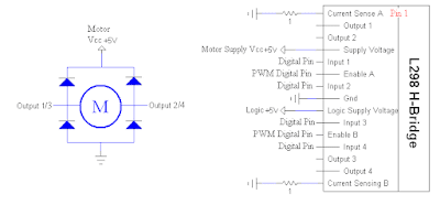
One thing that i had to figure out was how to control the thing... it has, as you can see, two inputs, two outputs and an enable pin for each of the two motors it can drive. Output 1/2 or 3/4 go to the motor, input 1/2 or 3/4 go to the Arduino along with a enable A/B pin (A is for motor 1 with input 1/2 and output 1/2). The two input pins can be regular digital pins as they just control the polarity of the motor(flip it to go in reverse). The Enable pin actually triggers on/off the motor and needs to be a PWM digital pin so that the Arduino can change the speed of the motor. Also, the Lm298 has a internal voltage drop of about 1.5v, so a 5v motor voltage worked great for the probably 3v(?) motor.
Scheme:
Code:
#define EnA 3 //enable A Pin
#define In1 6 //Input 1
#define In2 7 //input 2
void setup()
{
pinMode(EnA, OUTPUT);
pinMode(In1, OUTPUT);
pinMode(In2, OUTPUT);
}
void loop()
{
//rev speed up
for(int i = 0; i<255; i++)
{
//rev
digitalWrite(In1, LOW); //set dir
digitalWrite(In2, HIGH); //set dir
analogWrite(EnA, i); //enable mtr, half speed reverse
delay(20);
}
delay(1000); //full speed for 1 sec
//slow down
for(int i = 255; i>0; i--)
{
//rev
digitalWrite(In1, LOW); //set dir
digitalWrite(In2, HIGH); //set dir
analogWrite(EnA, i); //enable mtr, half speed reverse
delay(20);
}
//fwd speed up
for(int i = 0; i<255; i++)
{
//fwd
digitalWrite(In1, HIGH); //set dir
digitalWrite(In2, LOW); //set dir
analogWrite(EnA, i); //enable mtr, half speed fwd
delay(20);
}
delay(1000); //stay full speed for 1 sec
//slow down
for(int i = 255; i>0; i--)
{
//fwd
digitalWrite(In1, HIGH); //set dir
digitalWrite(In2, LOW); //set dir
analogWrite(EnA, i); //enable mtr, half speed fwd
delay(20);
}
//'stop'
digitalWrite(EnA, 0); //not enabled
delay(500);
}
Pics:
 |
| Pins bent to .1 spacing over center of breadboard |
 |
| All setup + running |
 |
| Diodes are hiding out behind the motor... |
Video:

No comments:
Post a Comment