A processing app reads the arrow keys and connects to the arduino bluetooth module using the internal computer Bluetooth. I put in a little parsing code for the serial output too: <1,0,0,0> the "<" and ">" represent the beginning and end of the datastream being sent. Boolean on/off logic is being used to determine which button is pressed. Think of it as; <fwd state, rev state, right state, left state> I also put in some safety checks so that forward and backward buttons can't both be on at once. The arduino the reads that data, splits it into individual values for forward, back, right, and left. Then I created a quick function that takes the split values and sets the buttons on the car remote to them(they are 0 or 1, low or high). So, then the remote sends the commands to the car and off it goes.
My final goal is to use a smartphone on the car that sends a live video feed back to the computer, and sends commands received over WiFi from the computer to the Arduino (the bluetooth sends the commands to the Arduino from the phone).
This code doesn't have to be used with Bluetooth; just connect your Arduino and tell processing to send the data to the Arduino serial port.
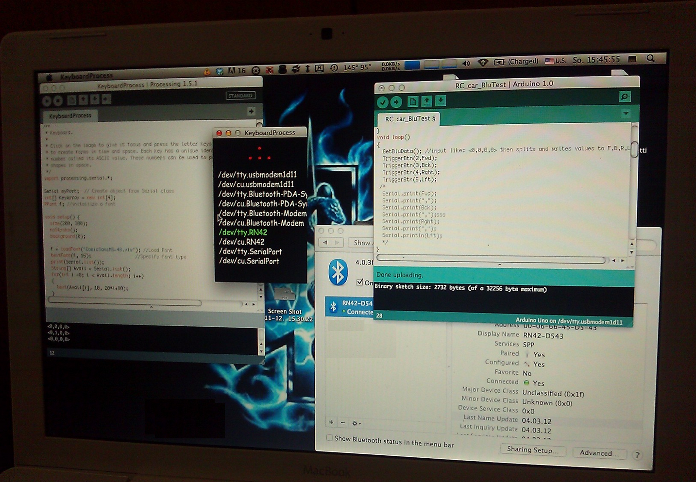
Pics:


Processing Code
import processing.serial.*;
Serial myPort; // Create object from Serial class
int[] KeyArray = new int[4];
int PrtChose = 6; //number of the serial port, starts at 0
PFont f; //initailize a font
void setup() {
size(200, 300);
noStroke();
background(0);
f = loadFont("ComicSansMS-48.vlw"); //Load Font
textFont(f, 15); //Specify font type
print(Serial.list());
String[] Avail = Serial.list();
for(int i =0; i < Avail.length; i++)
{
text(Avail[i], 10, 20*i+80); //print text of avaliable serial ports to app
}
fill(0,255,0);
text(Avail[PrtChose], 10, 20*PrtChose+80); //highlite the port in use
String portName = Serial.list()[PrtChose];
myPort = new Serial(this, portName, 115200);
}
void draw()
{
//chnage colors of 4 ellipses according to what keys are pressed
if (KeyArray[0] == 1)
{
fill(0, 255, 0);
}
else
{
fill(255, 0, 0);
}
ellipse(100, 20, 5, 5);
if (KeyArray[1] == 1)
{
fill(0, 255, 0);
}
else
{
fill(255, 0, 0);
}
ellipse(100, 40, 5, 5);
if (KeyArray[2] == 1)
{
fill(0, 255, 0);
}
else
{
fill(255, 0, 0);
}
ellipse(120, 40, 5, 5);
if (KeyArray[3] == 1)
{
fill(0, 255, 0);
}
else
{
fill(255, 0, 0);
}
ellipse(80, 40, 5, 5);
}
void keyReleased() //key released
{
if (key == 'w') //fwd, fwd has been let up, so set stop fwd message
{
KeyArray[0] = 0; //no longer pressed
}
if (key == 's') //down
{
KeyArray[1] = 0;
}
if (key == 'd') //right
{
KeyArray[2] = 0;
}
if (key == 'a') //left
{
KeyArray[3] = 0;
}
writeMsg(); //send updated state over serial
}
void keyPressed() //key pressed
{
if (key == 'w') //fwd
{
KeyArray[0] = 1; //fwd key pressed down, set forward command
}
if (key == 's') //down
{
KeyArray[1] = 1;
}
if (key == 'd') //right
{
KeyArray[2] = 1;
}
if (key == 'a') //left
{
KeyArray[3] = 1;
}
writeMsg();
}
void writeMsg()
{
//so both fwd/back, lft/rght dont activate at same time
if(KeyArray[0] == 1 && KeyArray[1] == 1)
{
KeyArray[0] = 0;
KeyArray[1] = 0;
}
if(KeyArray[2] == 1 && KeyArray[3] == 1)
{
KeyArray[2] = 0;
KeyArray[3] = 0;
}
//<0,0,0,0> <fwd,bck,rght,Lft>
myPort.write("<" + KeyArray[0] + "," + KeyArray[1] + "," + KeyArray[2] + "," + KeyArray[3] + ">"); //write to serial
println("<" + KeyArray[0] + "," + KeyArray[1] + "," + KeyArray[2] + "," + KeyArray[3] + ">"); //display in console
}
Arduino Code
int started = 0;
char inData[10];
int ended = 0;
char index = 0;
int final = 0;
boolean Fwd = 0;
boolean Bck = 0;
boolean Rght = 0;
boolean Lft = 0;
void setup()
{
Serial.begin(115200);
pinMode(13,OUTPUT);
}
void loop()
{
GetBluData(); //input like: <0,0,0,0> then splits and writes values to F,B,R,L
TriggerBtn(2,Fwd); //set digital pin 2 to value of Fwd ( HIGH or LOW)
TriggerBtn(3,Bck);
TriggerBtn(4,Rght);
TriggerBtn(5,Lft);
/*
Serial.print(Fwd);
Serial.print(",");
Serial.print(Bck);
Serial.print(",");sss
Serial.print(Rght);
Serial.print(",");
Serial.println(Lft);
*/
}
void TriggerBtn(int PinNum, boolean ButtonState)
{
if(ButtonState)
{
//turns on the button connected to the pin
digitalWrite(13,HIGH); //some key has been pressed, LED to show it
digitalWrite(PinNum, LOW); // PinNum is the number of the digital pin
pinMode(PinNum, OUTPUT); // Pull the signal low to activate button
}
else
{
//releases button connected to the pin
digitalWrite(13, LOW); //no key is being pressed, LED to show it
pinMode(PinNum, INPUT); // Release the button.
}
}
void GetBluData()
{
while(Serial.available() )
{
//finds < and >, the beginning and end of command
char aChar = Serial.read();
if(aChar == '<')
{
started = true;
index = 0;
inData[index] = '\0';
}
else if(aChar == '>')
{
ended = true;
}
else if(started)
{
inData[index] = aChar;
index++;
inData[index] = '\0';
}
else if (aChar =='*')
{
final = true;
}
}
if(started && ended)
{
const char* strDelimiter = ",";
char* p;
//<0,0,0,0>
//splits to individual ints
if ( p = strtok(inData, strDelimiter) )
{
Fwd = atoi(p);
}
if ( p = strtok(NULL, strDelimiter) )
{
Bck = atoi(p);
}
if ( p = strtok(NULL, strDelimiter) )
{
Rght = atoi(p);
}
if ( p = strtok(NULL, strDelimiter) )
{
Lft = atoi(p);
}
// Get ready for the next time
started = false;
ended = false;
index = 0;
inData[index] = '\0';
}
}
hello, i was wondering if it is possible to connect a h-bridge circuit with transistors to the outgoing arduino output pins which are connected to the rc transmiter, and can you please tell me which are the output pins from the arduino i can't see them in the code
ReplyDeletepin 2 is forward on the remote...
DeleteTriggerBtn(2,Fwd); //set digital pin 2 to value of Fwd ( HIGH or LOW)
TriggerBtn(3,Bck);
TriggerBtn(4,Rght);
TriggerBtn(5,Lft);
you dont need a transistor / h bridge to trigger the buttons on the remote:
if(ButtonState)
{
//turns on the button connected to the pin
digitalWrite(13,HIGH); //some key has been pressed, LED to show it
digitalWrite(PinNum, LOW); // PinNum is the number of the digital pin
pinMode(PinNum, OUTPUT); // Pull the signal low to activate button
}
but if you mean the arduino pins to the actual motors on the car, then yes.
Very useful thing here! Thank you very much for posting it, there is not much stuff like that around the internet!
ReplyDeleteIf I wanted to implement this idea using a MATLAB GUI as the controlller.....what changes would I have to make to either the processing code or the Arduino code? I'm trying to do a 3 phase project. Phase 1 is to control the car remotely (USB), Phase 2 is to control it wirelessly. Phase 3 is to let the vehicle operate somewhat autonomously.
ReplyDeletefor phase 1 if you mean using serial over usb, there wouldnt really be any changes. ive never used mathlab so i have no idea really. sorry.
DeleteArray out of bound exception error in " text(Avail[PrtChose], 10, 20*PrtChose+90)"
ReplyDeleteHi how can I directly connect the arduino uno into the pins of the receiver board instead of the transmitter/controller board?
ReplyDelete